If you are a member of the “maker scene” and have already realized one or the other project with the Arduino, you have probably already reached the point that even an Arduino Nano is simply too big for your project. Besides the actual microcontroller, various peripherals are also packed onto the Arduino board.
Here it is worthwhile to take a look at the inexpensive microcontroller family ATtiny from Atmel. Depending on the project, controllers with 8 to 32 pins are available.
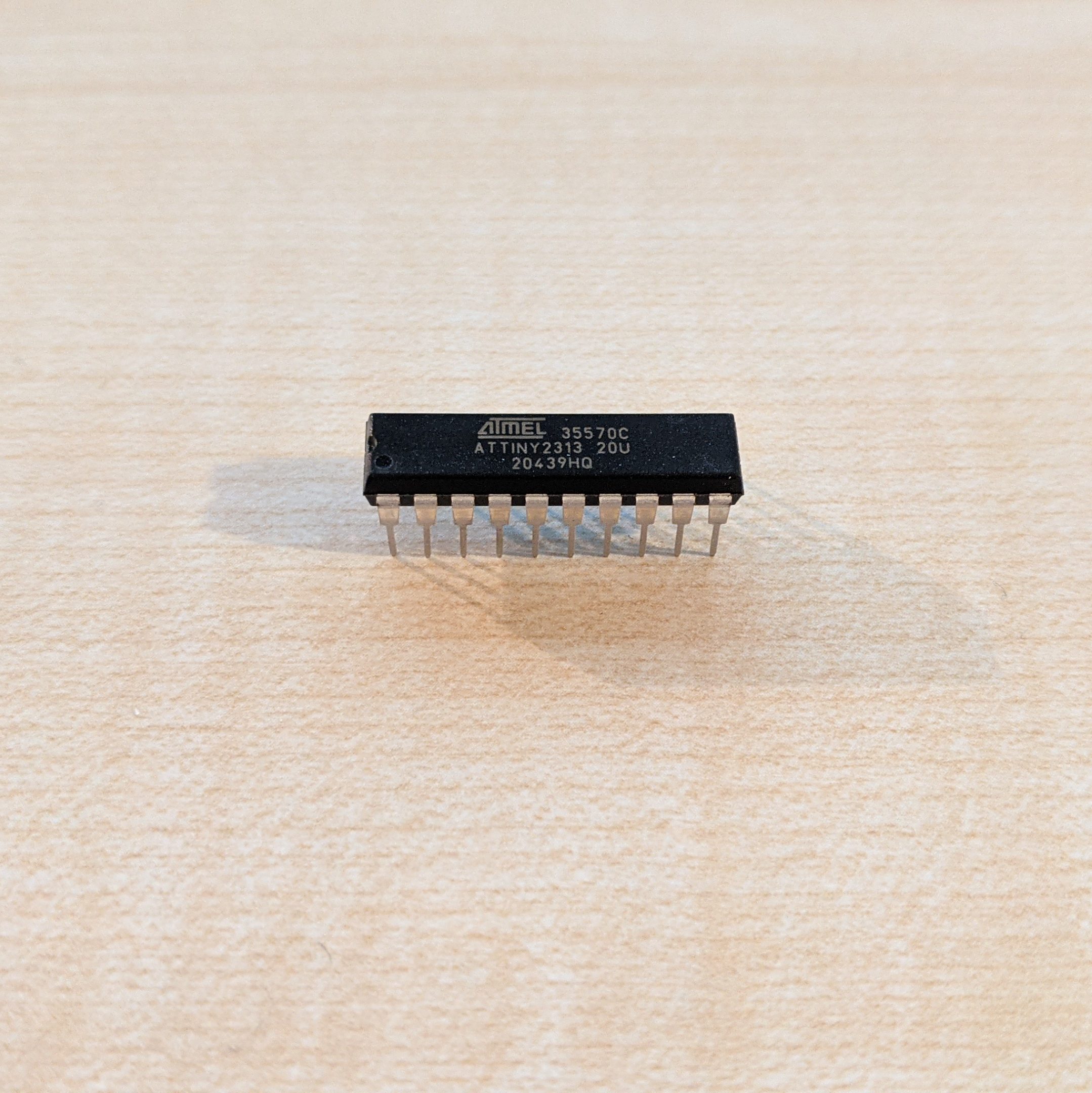
The special thing about the ATtiny for me is that it can be used for own circuits without any complex external circuitry. In practice, this means: program, apply voltage, done. Furthermore the ATtiny can handle very variable supply voltages. The 2313 can be supplied with 2.7-5.5V DC. Thereby it has 18 I/O pins. The Tiny can be operated with an internal clock of up to 20MHz. In the default setting (keyword: fuses), however, an internal divider is used, which means that the Tiny works with an internal clock of 1MHz (note: which is often sufficient for a large part of typical Maker projects).
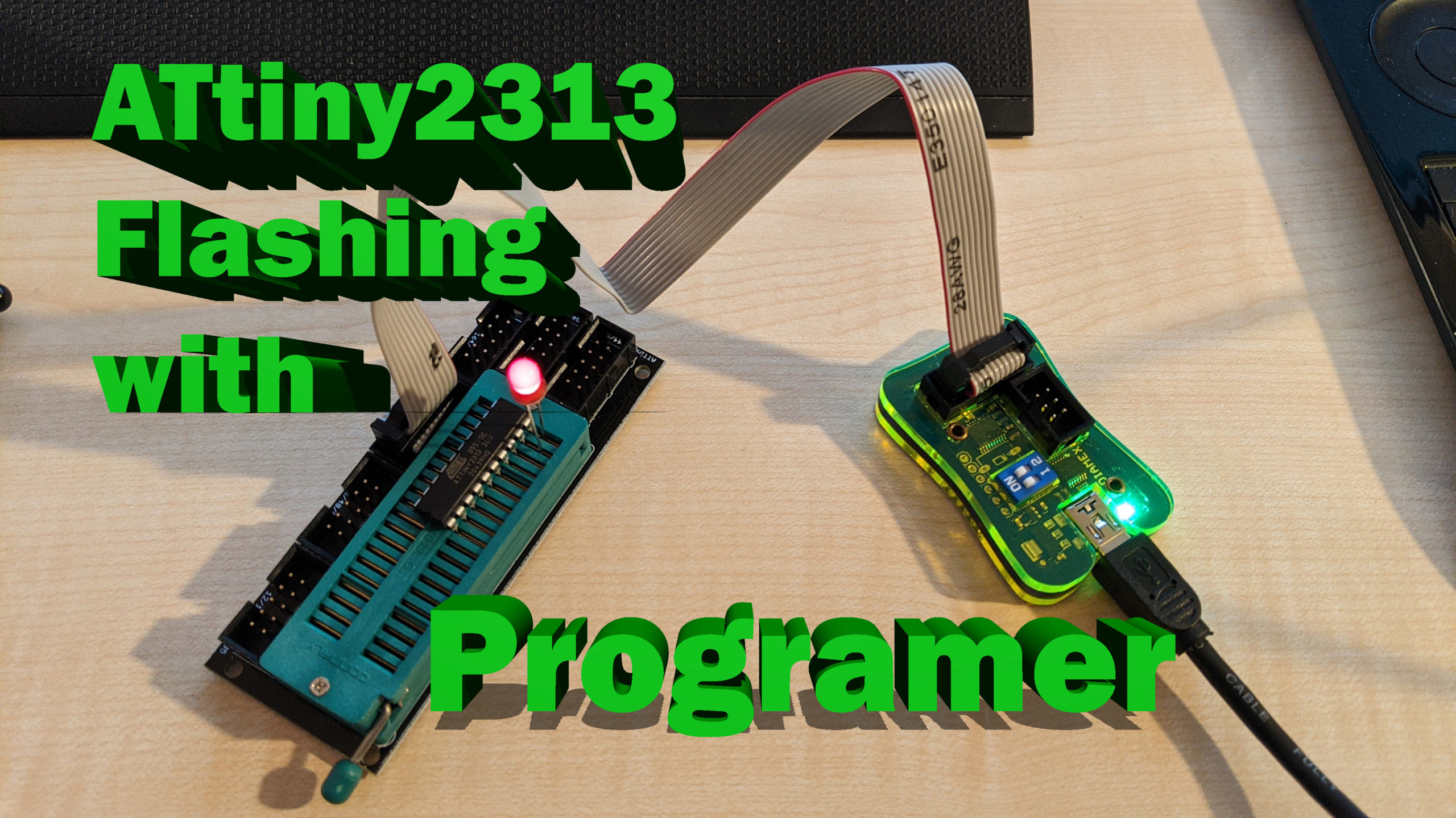
But since it does not come on a lavishly equipped board with USB interface and bootloader, the question now is: how is it programmed? Personally, I have meanwhile turned to C++ or Arduino, since I don’t get to program very often anyway. Therefore I was looking for a way to program the Tiny in Arduino. On the net I came across numerous instructions (mostly for the smaller ATtiny85), how to program the ATtiny with the help of a misused Arduino Uno as ISP. This solution was not comfortable enough for me, so I bought a cheap AVR-ISP Programer with a swivel lever module for inserting the microcontroller from an online mail order company.
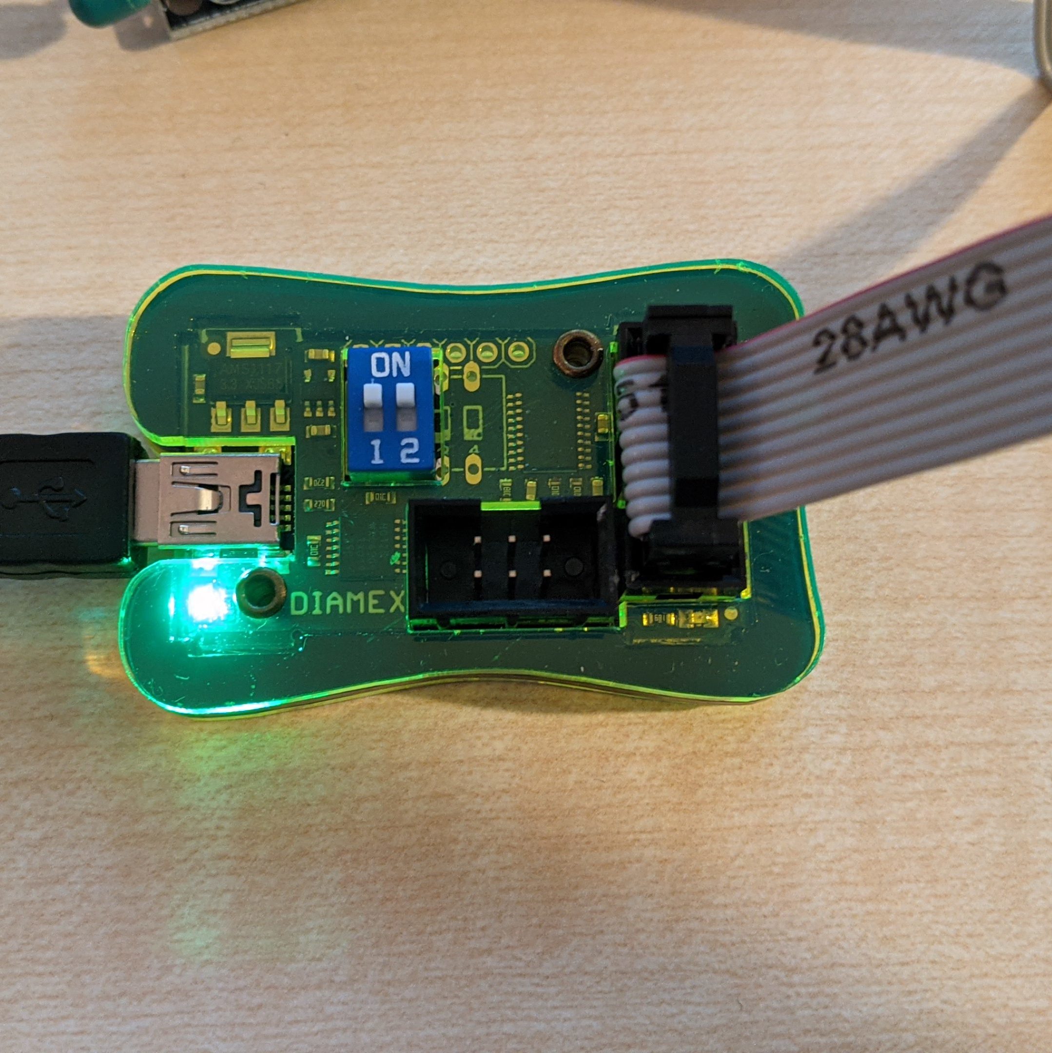
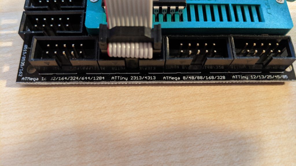
Windows 10 recognized and installed the drivers for the programmer without any problems. Because the programmer has to supply the ATtiny with voltage for programming, the DIP switch 1 is set to ON. The DIP switch 2 sets the voltage level (OFF=3,3V, ON=5V). Since the ATtiny can handle both voltages, I also set switch 2 to ON. The supplied ribbon cable is connected with one side to the 10 pin header of the programmer and with the other side to the correspondingly labeled port of the swing lever module (ATTiny 2313/4313).
Now just connect the programmer to the USB interface of the PC… and ready.
To get an Arduino program on the Tiny, you have to choose a programming platform (IDE). I describe the programming once with the widely used Arduino IDE and the (in my opinion) somewhat more comfortable IDE PlatformIO based on Visual Studio Code from Microsoft.
Before the Arduino IDE can be persuaded to flash the controller, a suitable hardware library must be installed. To do this, go to “Tools” -> “Board” -> “Board Manager” in the Arduino IDE and search for “ATTinyCore” by Spence Konde. I have installed the current version 1.4.1.
Then the correct microcontroller, chip, clock, port and last but not least the programmer must be selected:
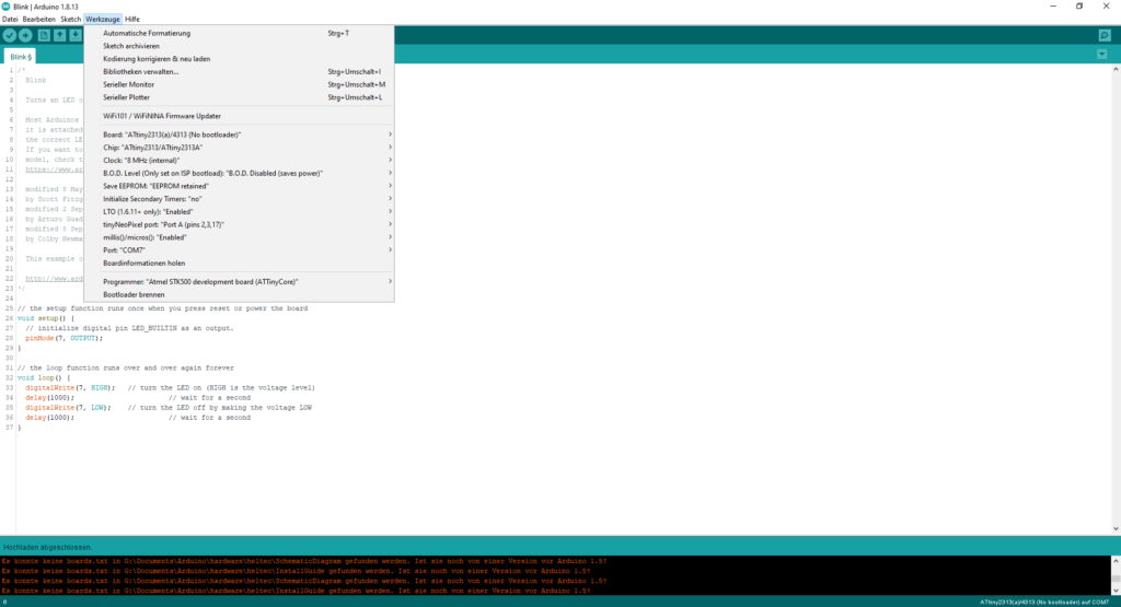
As first example program I selected “Blink.ino”, where I selected as output the pin 7 of the ATtiny for the LED. Now one more click on the upload button… and the LED blinks every second!
With PlatformIO the way is similarly simple, if you have made the appropriate entries in the configuration file platformio.ini of the Blink project:
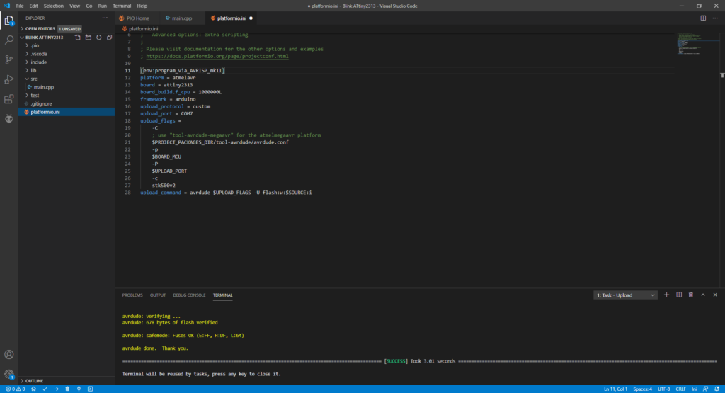
A corresponding example configuration for the programer can already be found in the PlatformIO documentation and only needs to be adapted to the microcontroller used:
[env:program_via_AVRISP_mkII]
platform = atmelavr
board = attiny2313
board_build.f_cpu = 1000000L
framework = arduino
upload_protocol = custom
upload_port = COM7
upload_flags =
    -C
    ; use "tool-avrdude-megaavr" for the atmelmegaavr platform
    $PROJECT_PACKAGES_DIR/tool-avrdude/avrdude.conf
    -p
    $BOARD_MCU
    -P
    $UPLOAD_PORT
    -c
    stk500v2
upload_command = avrdude $UPLOAD_FLAGS -U flash:w:$SOURCE:i
After selecting the appropriate serial port of the programmer under upload_port, only the board (attiny2313) and the clock frequency of 1MHz (board_build.f_cpu = 1000000L) must be entered. For the operation with a higher clock frequency the fuses of the controller must be adapted.
Have fun with Making!