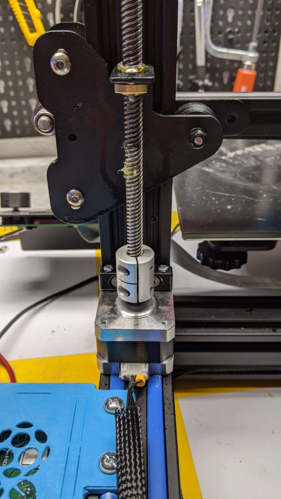
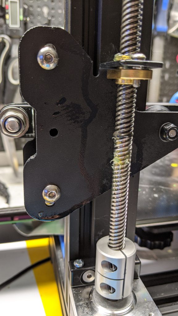
For a long time I wanted a second drive unit for my Z-axis as an upgrade for my Geeetech A10. In November the time had finally come. Since there was no ready-made upgrade kit for the Geeetech, I used one for the CR-10 / Ender 3. With a few mechanical adjustments, the kit could also be attached to the Geeetech A10.
In addition to the additional Nema 17 stepper motor and the mechanical components for mounting on the printer, the set also included a Y-cable. I used this cable at the beginning to connect both motors to the mainboard and the TMC2208 stepper motor driver installed on it.
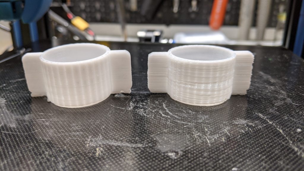
I excitedly printed the first part with the “upgraded Z-axis” … and was unfortunately disappointed. The print image was worse than with just one drive unit (see picture).
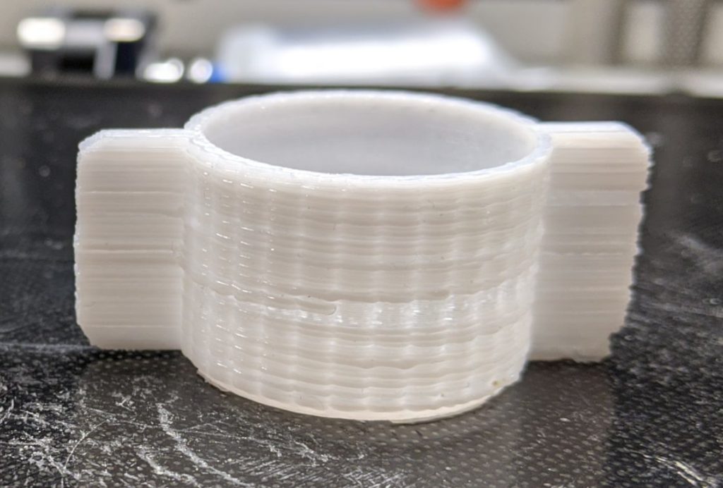
The print showed clear gaps in the Z direction. Sometimes the filament was actually squeezed out. Everything indicated bad or irregular positioning in the Z direction. My first guess was that the alignment of the X axis was not optimal and that the two Z axis spindles could have tilted as a result. None. The spindles of the Z axis were parallel and could also be easily adjusted.
But wait: when moving the Z-axis, the printer sounded a little rougher than before the conversion. A mechanical weak point could not be found. Perhaps the stepper motor driver was unable to cope with the second motor? Not quite!
Both motors were connected in parallel to the stepper motor driver via the Y cable:
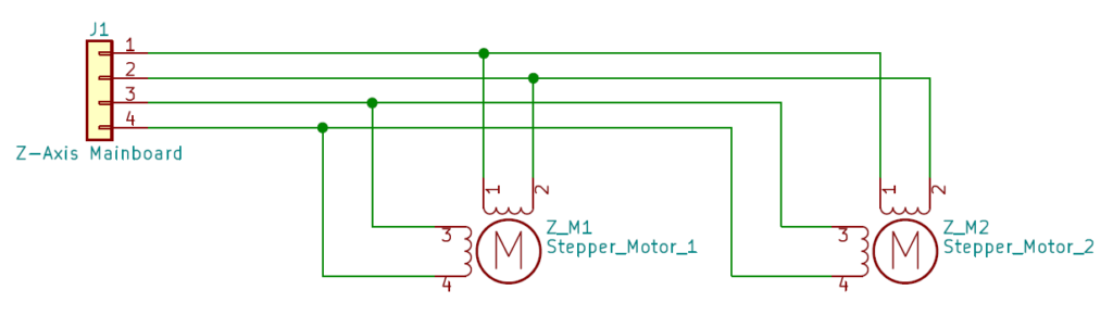
Sketch: Connection of the motors with the supplied Y cable (parallel connection)
The stepper motor driver is basically a constant current source. This means that it supplies a constant current at each of the two outputs for the windings of the stepper motors; practically independent of the load connected to it. By connecting two identical motors in parallel on one stepper motor driver, the current supplied is divided between the two coils at the nodes. This means that each of the two motors only receives half of the nominal current. This leads to a lack of torque on the two motors, which is evident from the print image described above.
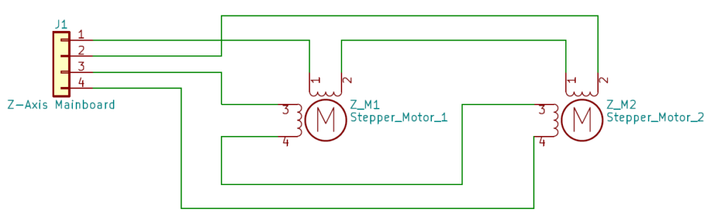
The idea was to simply connect both pairs of windings in series instead of in parallel:
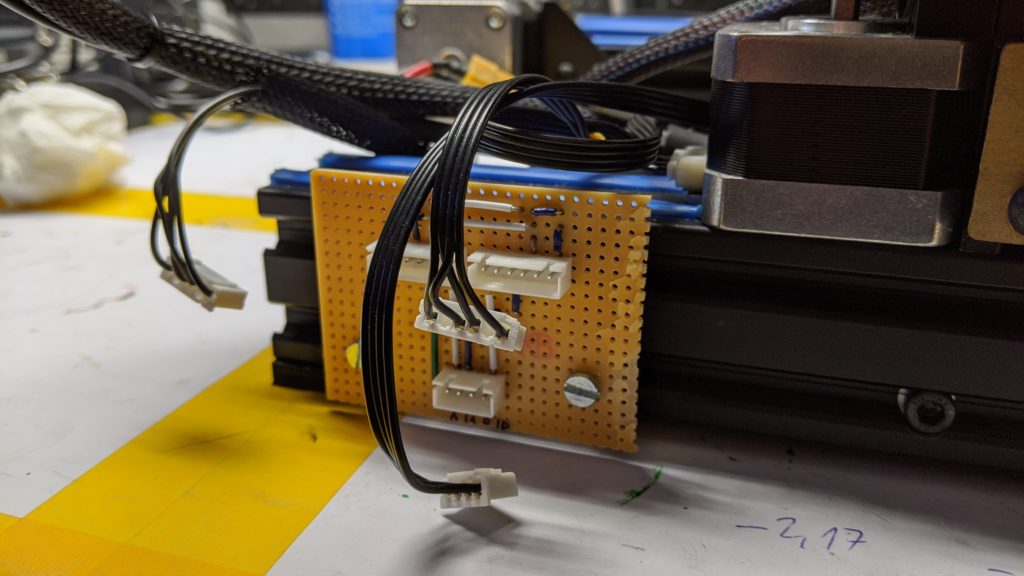
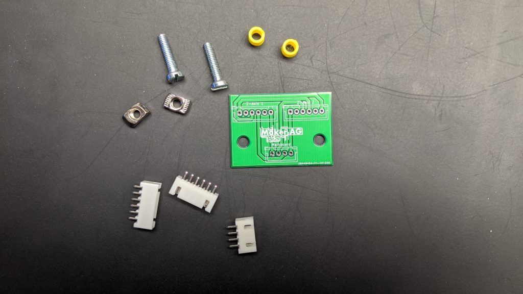
In order to achieve this, I quickly made a corresponding test board with the help of a breadboard, some bridge wires and three plugs:
The current result was incredible! The engines now run just as quietly as the individual Z-engine before the conversion. The Z-axis is now practically silent. In addition, the Z-axis is now much more stable, which enables prints to be printed at higher speeds while maintaining the same quality:
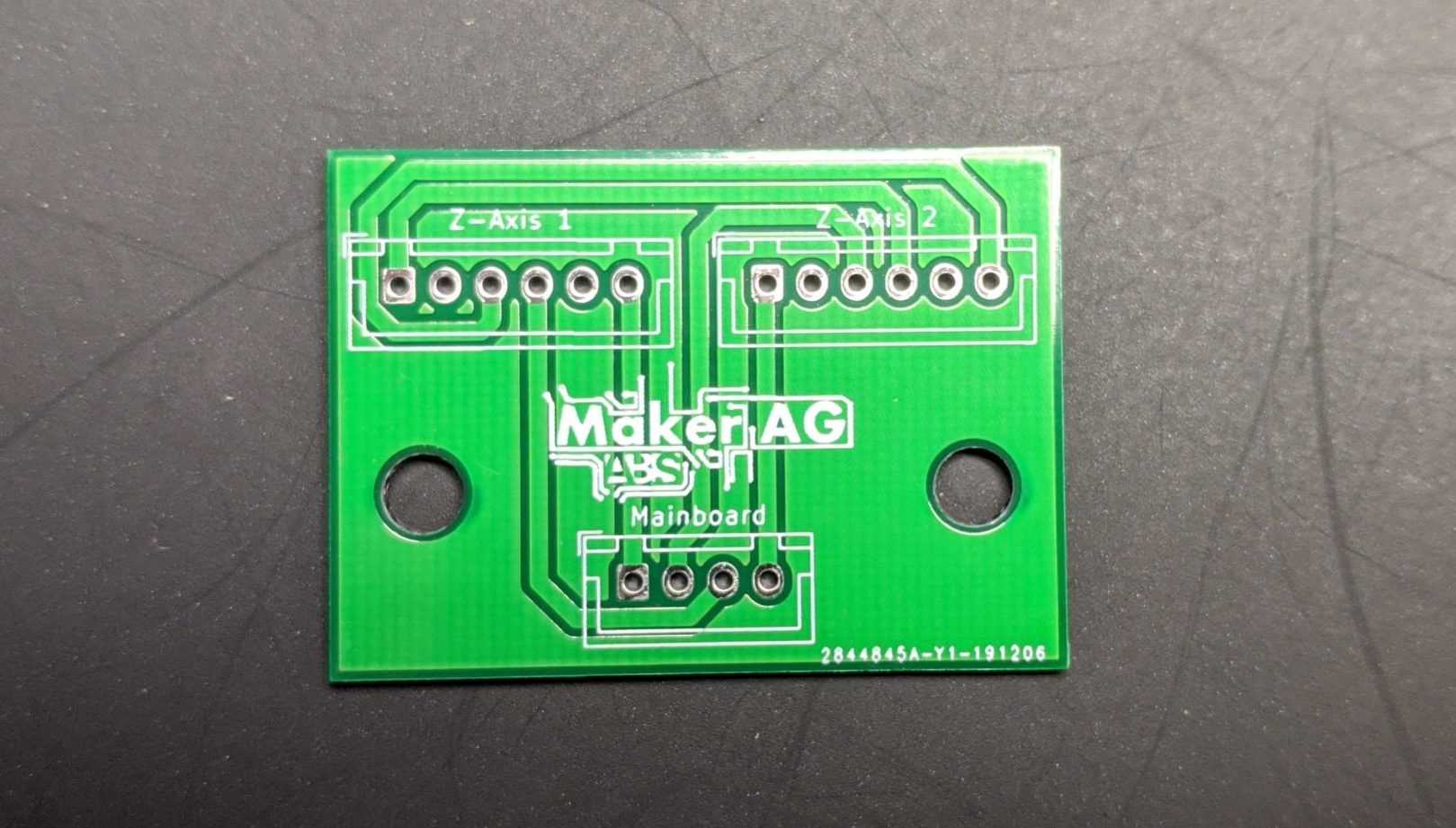
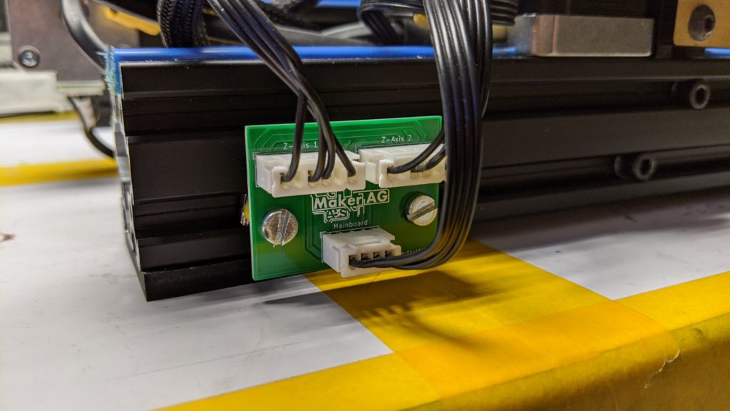
Since the board has proven itself so well, but there is no comparable board on the market for the series connection of Z-axis motors, I quickly designed and produced one myself.
If you are interested in such a set, please feel free to contact me: andre@makerag.de
However, the boards are currently sold out until further notice.
Update 2020-08-05: Boards are available again 🙂
However, the boards are currently sold out until further notice.
How much?
Thanks
Hello John, unfortunately we currently have no more circuit boards. Sorry.
Nice and informative.
Just a thought did you try to just double the current on the driver when you was running the steppers in parallel?
Kind regards/Stefan
Hello Stefan, theoretically this could have worked, but unfortunately the drivers can’t deliver such high currents according to the data sheet.